从隔壁老王电子那里花两块五淘来的pos机,拆开里面有锂电池一块,屏幕一块,蜂鸣器一个,主控无资料,蓝牙芯片也无资料,NFC芯片丝印磨掉了,猜测NFC是MFRC522,对比走线和数据手册,发现天线部分引脚相同,于是拆下来焊接到RC522模块上,居然猜对了!
查看数据手册:https://www.semiee.com/file/backup/NXP-MFRC522.pdf

通讯模式
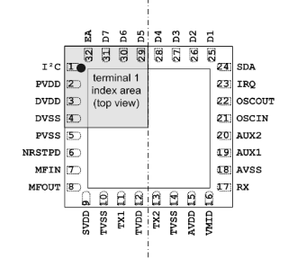
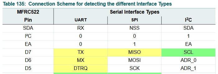
通过Datasheet了解到MFRC522可以支持3种通讯方式:UART、SPI、I2C。
1.当I2C脚为高电平时,芯片工作在I2C模式下,此时EA脚用来设置I2C的自定义地址是3bit还是7bit,当EA=1,芯片地址是[0] [ADR_5~ADR_0];当EA=0,芯片地址是[0101] [ADR_2~ADR_0].
2.当I2C脚为低电平时,芯片工作在UART或SPI模式下,此时EA=0,选择UART模式,EA=1,选择SPI模式。

电路
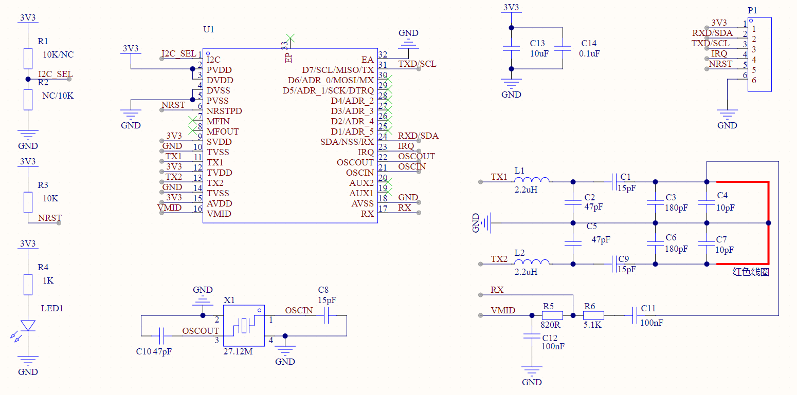
由于UART和I2C引脚相同,所以直接做成UART和I2C复用型模块。把EA脚接低电平,由I2C脚来选择是UART或是I2C。
通过R1、R2选择I2C或UART模式。

PCB设计
在PCB上通过焊接R1或R2来选择UART或是I2C模式,在PCB背面可以看到UART和I2C的引脚是复用的。
其中U1、L1、L2、X1是POS机上拆下来的。
白色方框下NFC线圈


测试
使用Arduino+MF522_I2C库测试通过

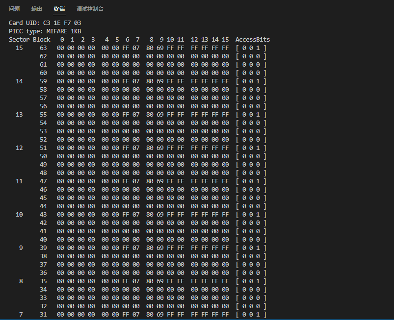
读取到卡片信息

下载
工程文件在这里:https://oshwhub.com/lihooo/rc522-demo
程序:Arduino+MF522_I2C库
void setup() {
    Serial.begin(9600); // Initialize serial communications with the PC
    Wire.begin(); // Initialize I2C
    mfrc522.PCD_Init();     // Init MFRC522
    ShowReaderDetails();    // Show details of PCD - MFRC522 Card Reader details
    Serial.println(F("Scan PICC to see UID, type, and data blocks..."));
}

void loop() {
    // Look for new cards
    if ( ! mfrc522.PICC_IsNewCardPresent()) {
            return;
    }
    // Select one of the cards
    if ( ! mfrc522.PICC_ReadCardSerial()) {
        return;
    }else

    // Dump debug info about the card; PICC_HaltA() is automatically called
    mfrc522.PICC_DumpToSerial(&(mfrc522.uid));
}